

What Is a Metal Detector Kit?
A metal detector kit is a DIY electronic assembly package that includes the necessary components and instructions for building a functional metal detector. Typically designed for hobbyists and electronics enthusiasts, these kits offer an engaging and educational experience, allowing individuals to construct their own metal detectors from scratch. Users gain insights into electronics and sensor technology while enjoying the satisfaction of creating a useful device capable of detecting metallic objects. These kits often cater to various skill levels, making them accessible to both beginners and experienced DIY enthusiasts interested in exploring the world of electronic circuitry.
LuckScout 4.5V Metal Detector Kit
This metal detector kit that can be bought on this website is a simply DIY electronic project that is not just something to do and it can be used in the real world to detect metals too, because although it is simple and small, it works strongly and has a relatively reasonable range of over 5cm to locate metals, even when they are covered by nonmetal materials like plastic. Don’t worry if you haven’t done an electronic project like this before. We have provided full printed and video instructions to solder and assemble different parts of our metal detector kit in less than an hour.
Features of the LuckScout Metal Detector Kit
1. Easy to Complete and Launch
It is consists of 18 electronic parts that are ready to become soldered on the printed circuit board that is also one of these parts that comes with our metal detector kit, as per the instructions we have provided.
2. A Special PCB
The printed circuit board or PCB that comes with this metal detector kit has a complete roadmap for the positions of the parts that have to be soldered on this board. Therefore, those who know different electronic pieces like capacitors, resistors, transistors, and so on, just the PCB is enough to assemble and run the metal detector. In spite of this, we have provided complete paper and video instructions that enable everyone to make the metal detector work.
Additionally, the PCB of our metal detector kit is a “plated” one which is more professional and much easier to solder.
A plated printed circuit board is a type of circuit board where the conductive pathways on the board are coated or plated with a layer of metal. The metal plating is typically applied to the surface of the board and serves to create the conductive traces that connect different components and elements on the PCB. The metal plating on the PCB provides conductivity, allowing electrical signals to flow between various components and parts of the circuit. Our metal detector plated PCB provides a stable and reliable platform for mounting the electronic component of resistors, capacitors, integrated circuits to make this kit work within the shortest possible time.
3. Our Tools
If you haven’t assembled an electronic kit like our metal detector and therefore don’t know which tools are necessary or lack them in your toolbox, we have the best options for you. You can purchase the best and most suitable soldering tools along with our metal detector kit if you wish. This is explained below.
Metal Detector Kit Assembly Instructions
You can either watch the video below or refer to the step-by-step explanations provided to learn how to assemble our metal detector kit. Additionally, find instructions on ordering the kit and necessary tools at the end of this article.
1. Metal Detector PCB
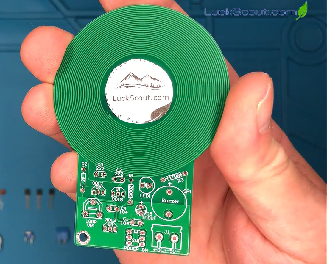
The metal detector PCB, or printed circuit board, is the first component you need to familiarize yourself with. There are 16 electronic components that must be soldered onto this board, as demonstrated in the accompanying video:
2. Ceramic Capacitors
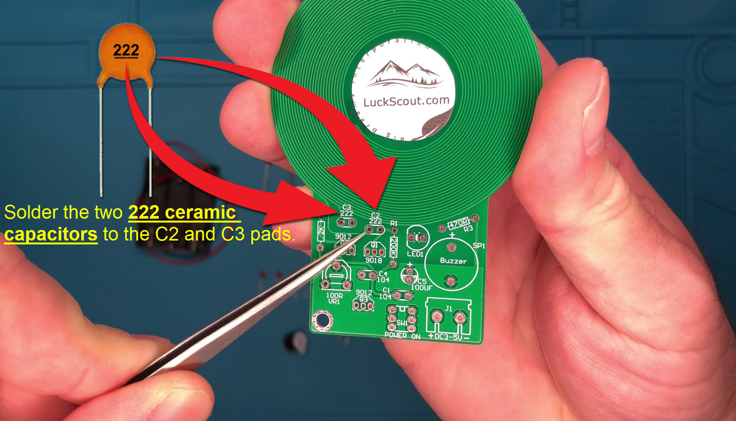
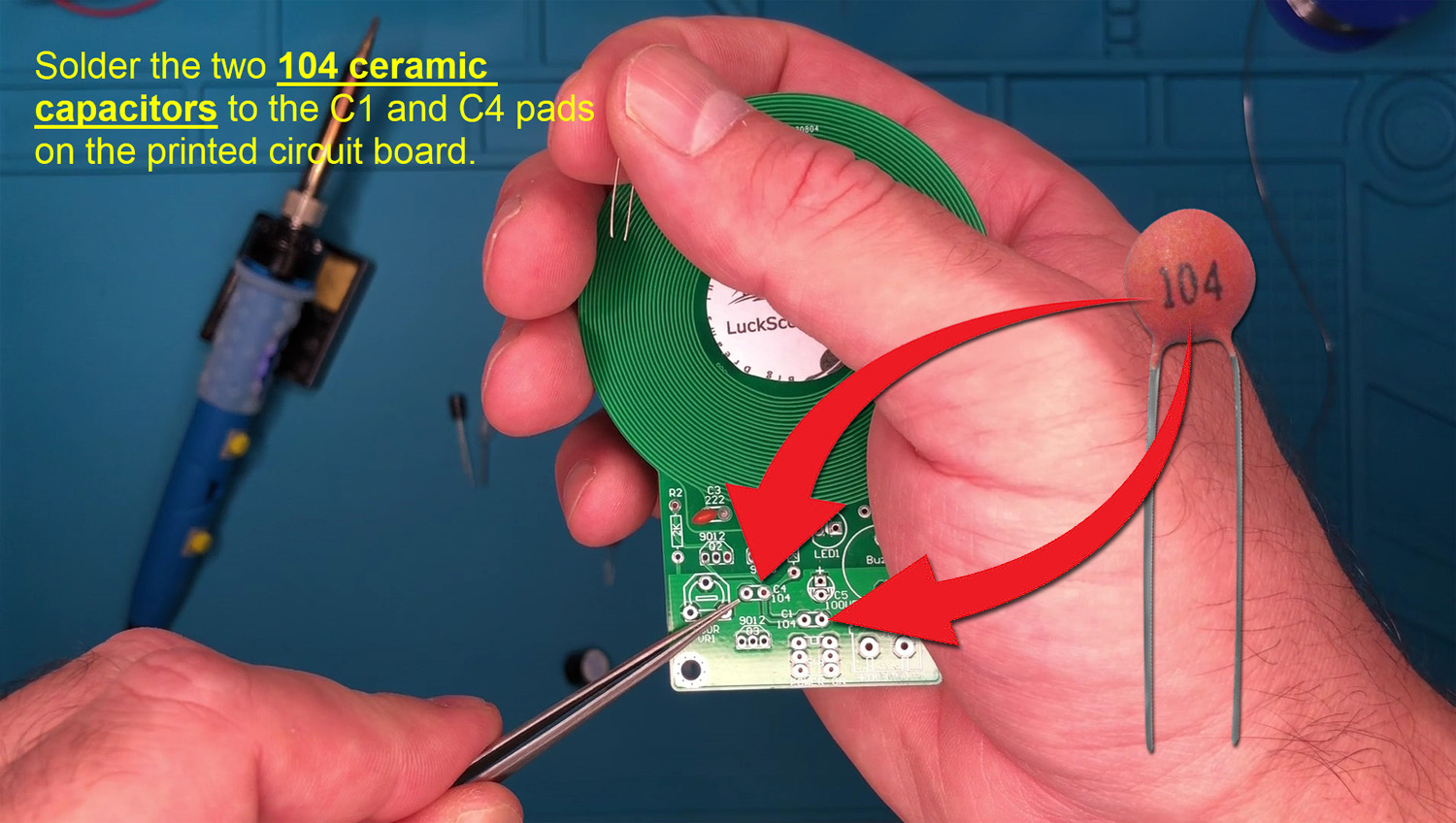
There are two 222 and two 104 ceramic capacitors that need to be soldered onto the PCB of our metal detector kit. The 222 and 104 ceramic capacitors, often denoted as 22nF or 0.022μF, respectively, are specific types of capacitors that serve various purposes in electronic circuits, including our metal detector kits. Capacitors, in general, store and release electrical energy, playing roles such as smoothing signals, filtering noise, and coupling or decoupling components.
In our metal detector kit, solder the two 222 ceramic capacitors onto the C2 and C3 pads on the PCB:
And, solder the two 104 ceramic capacitors onto the C1 and C4 pads on the PCB:
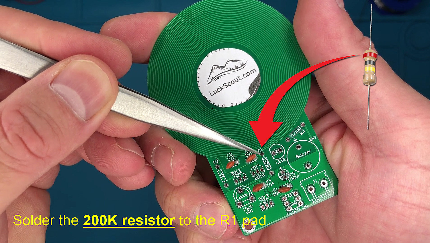
3. 200K Metal Film Resistor
In our metal detector kit, there are three metal film resistors, one of which is a 200K metal film resistor. The “metal film” designation refers to the construction of the resistor. Metal film resistors are manufactured by depositing a thin film of metal, often nickel-chromium or similar alloys, onto a ceramic substrate. This manufacturing process provides stability, accuracy, and low noise in comparison to other types of resistors.
A 200K metal film resistor is a type of resistor with a resistance value of 200,000 ohms (200 kilohms or 200KΩ). To distinguish this resistor from the other two in our metal detector kit, look for the color bands: red, black, yellow, and gold
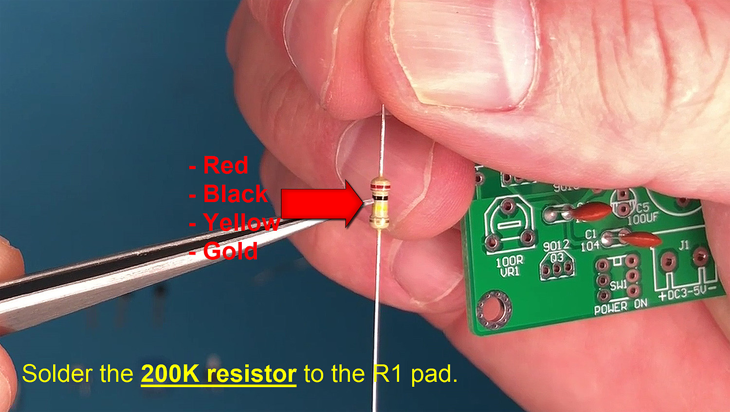
In our metal detector kit, solder the 200K metal film resistor onto the R1 pad on the PCB:
4. 2K Metal Film Resistor
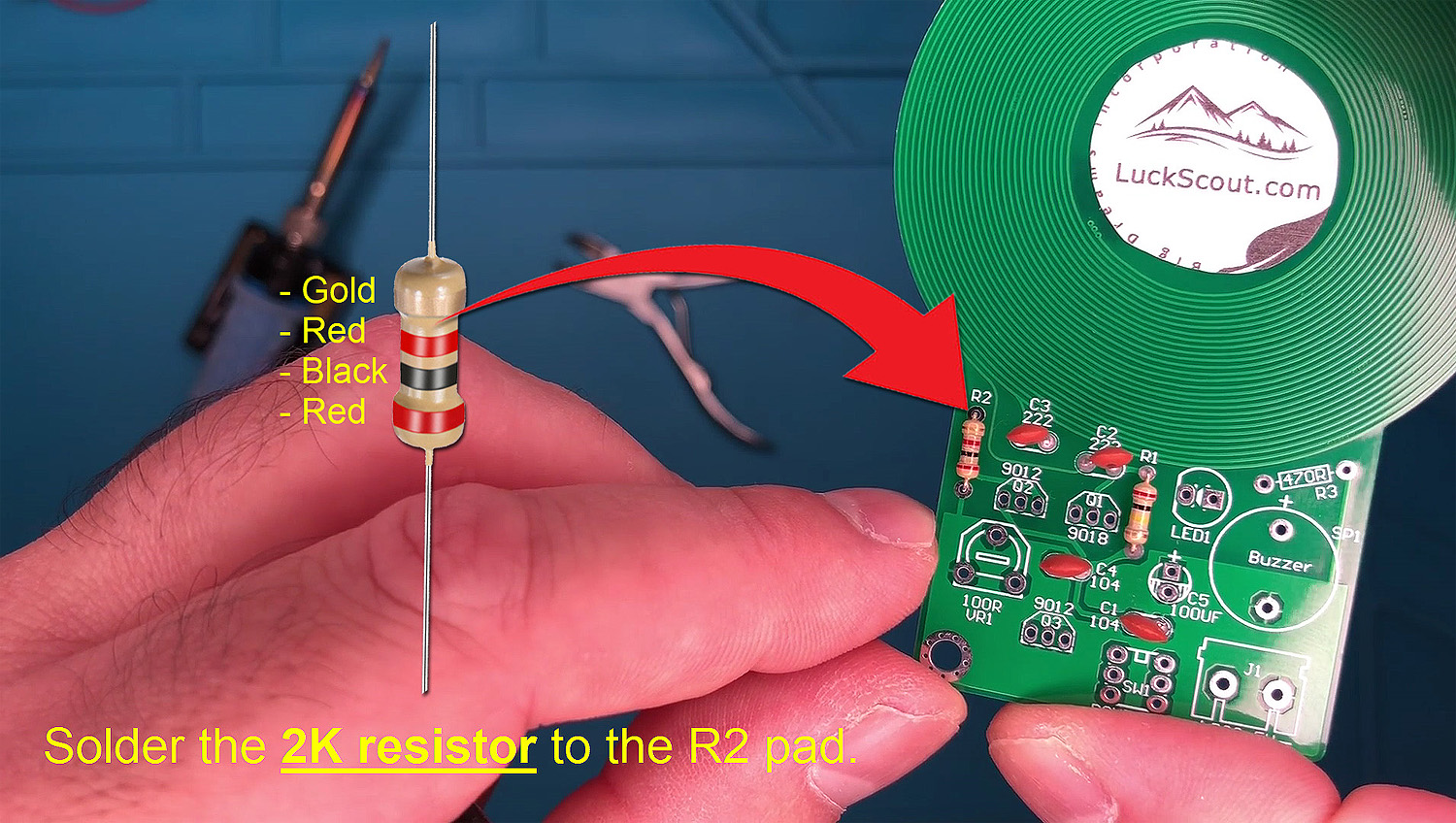
A 2K metal film resistor is a type of resistor with a resistance value of 2,000 ohms (2 kilohms or 2KΩ). To distinguish this resistor from the other two resistors in our metal detector kit, look for the color bands: gold, red, black and red
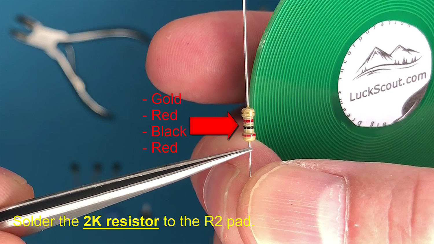

In our metal detector kit, solder the 2K metal film resistor onto the R2 pad on the PCB:
5. 470-ohm Metal Film Resistor
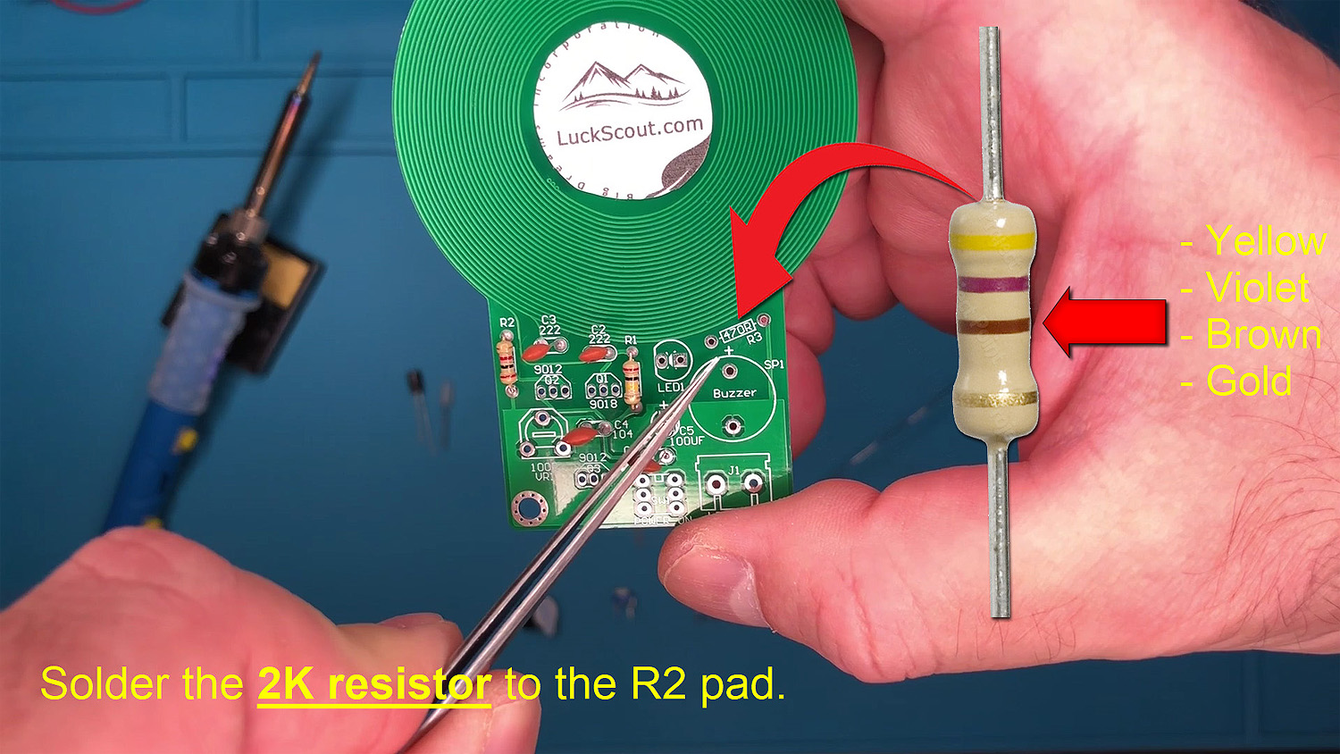
A 470-ohm metal film resistor is a type of resistor with a resistance value of 470 ohms. To distinguish this resistor from the other two resistors in our metal detector kit, look for the color bands: yellow, violet, brown and gold
In our metal detector kit, solder the 2K metal film resistor onto the 470ohm R3 pad on the PCB:
6. S9018 Transistor
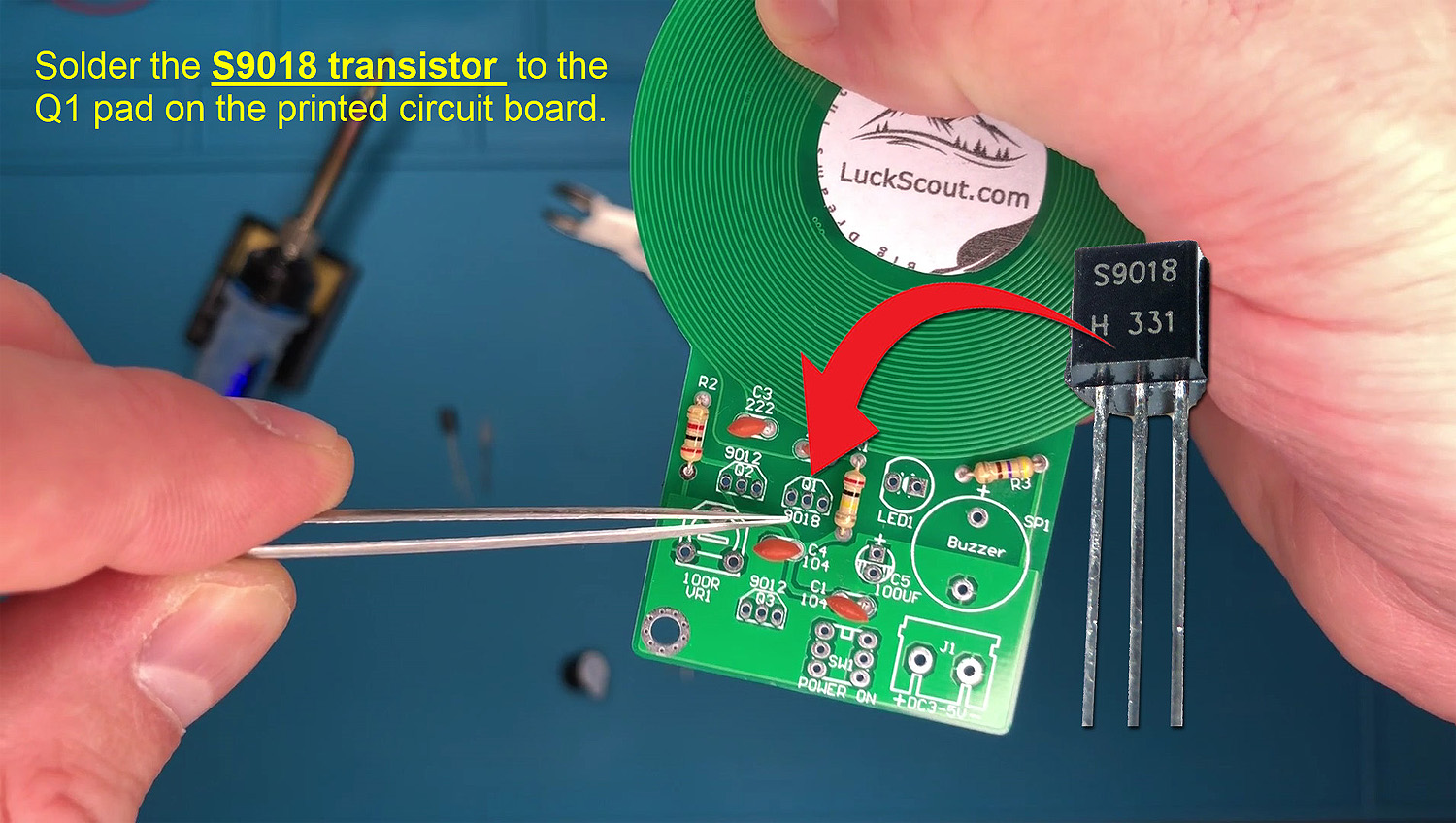
There is one S9018 transistor in our metal detector kit that needs to be soldered onto the Q1 pad. The S9018 transistor is a general-purpose NPN bipolar junction transistor (BJT). As an NPN transistor, it consists of three layers of semiconductor material: a negatively-doped layer (N-type) sandwiched between two positively-doped layers (P-type). Solder the single S9018 transistor provided with our metal detector kit onto the Q1 pad:
7. S9012 Transistors
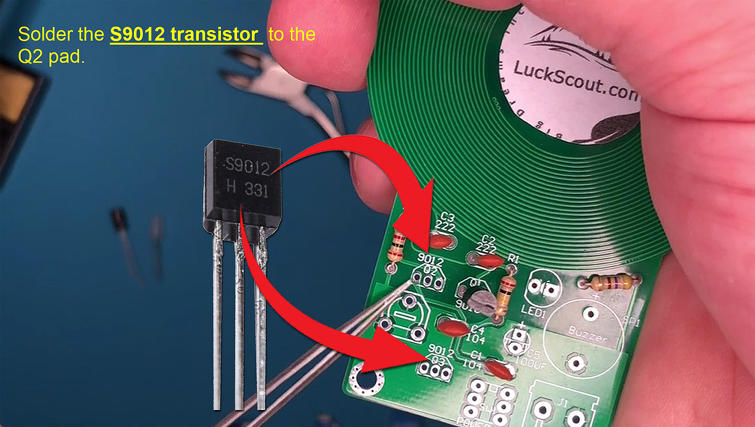
There are two S9012 transistors in our metal detector kit that need to be soldered onto the Q2 and Q3 pads:
8. 100µF Electrolytic Capacitor
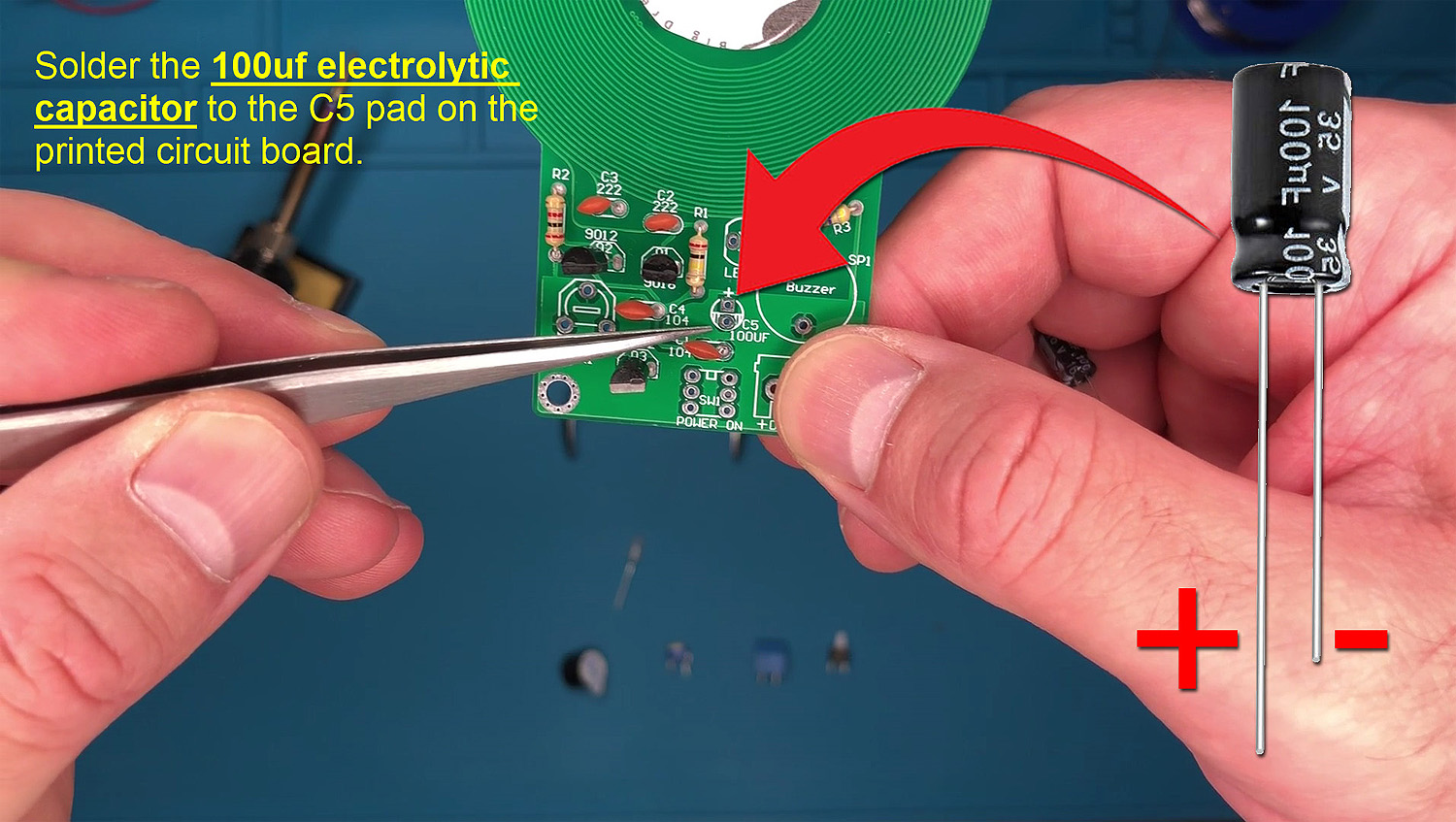
A 100µF (microfarad) electrolytic capacitor is a type of capacitor with a capacitance value of 100 microfarads. One of these electronic components is included in our metal detector kit and needs to be soldered onto the C5 pad. Please note that, unlike other components, the 100µF electrolytic capacitor has anode and cathode legs that must be soldered in the correct positions on the PCB. The longer anode leg should be placed where it is marked with a ‘+’ on both the PCB and the C5 pad:
9. Red LED Diode 5mm
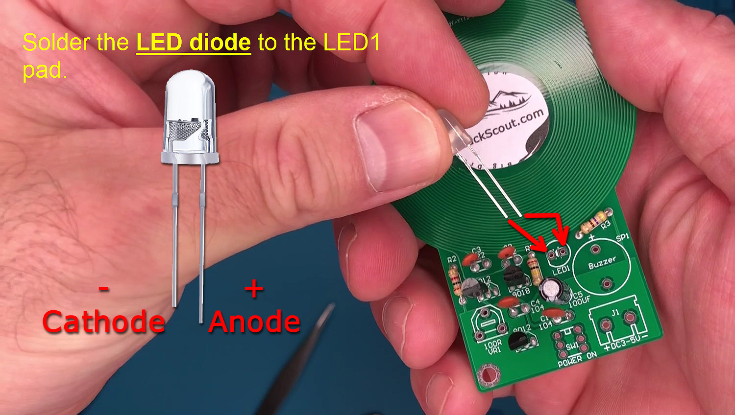
A ‘Red LED Diode 5mm’ refers to a light-emitting diode (LED) with a 5mm diameter that emits red light. There is one of these LEDs in the metal detector kit that needs to be soldered onto the LED1 pad.
Please note that, similar to the electrolytic capacitor, LED diodes also have anode and cathode legs that must be soldered in the correct position onto the pad. The cathode leg is shorter, and the LED bulb has a flat side above the cathode leg. On the PCB, the LED1 position is marked with a circle that has a flat side on the left. Ensure you insert the cathode leg, which is shorter, to the left side:
10. 9x12mm Buzzer
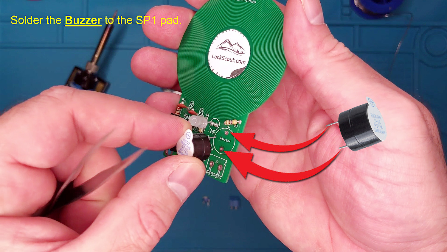
It is very easy to install the buzzer. This component will buzz when the metal detector kits detects a metal. The buzzer has two legs. One of them is marked with a ‘+’ on the buzzer, while there is also a ‘+’ on the PCB and at the SP1 pad, which is where the buzzer has to be soldered:
It is very easy to install the buzzer. This component will buzz when the metal detector kit detects metal. The buzzer has two legs. One of them is marked with a ‘+’ on the buzzer, while there is also a ‘+’ on the PCB and at the SP1 pad, where the buzzer has to be soldered:
11. 100R Potentiometer
The 100R potentiometer is a crucial component in the metal detector, allowing you to adjust the detector’s sensitivity, as demonstrated in the video below. Typically, the metal detector begins buzzing when first turned on, with the potentiometer at its initial position. However, you need to turn it to the right using a screwdriver, as shown in the video, to optimize sensitivity. Despite its importance, the potentiometer is straightforward to solder and install, unlike some other components such as the electrolytic capacitor or LED diode. It has three legs that need to be placed in three holes onto the VR1 pad:
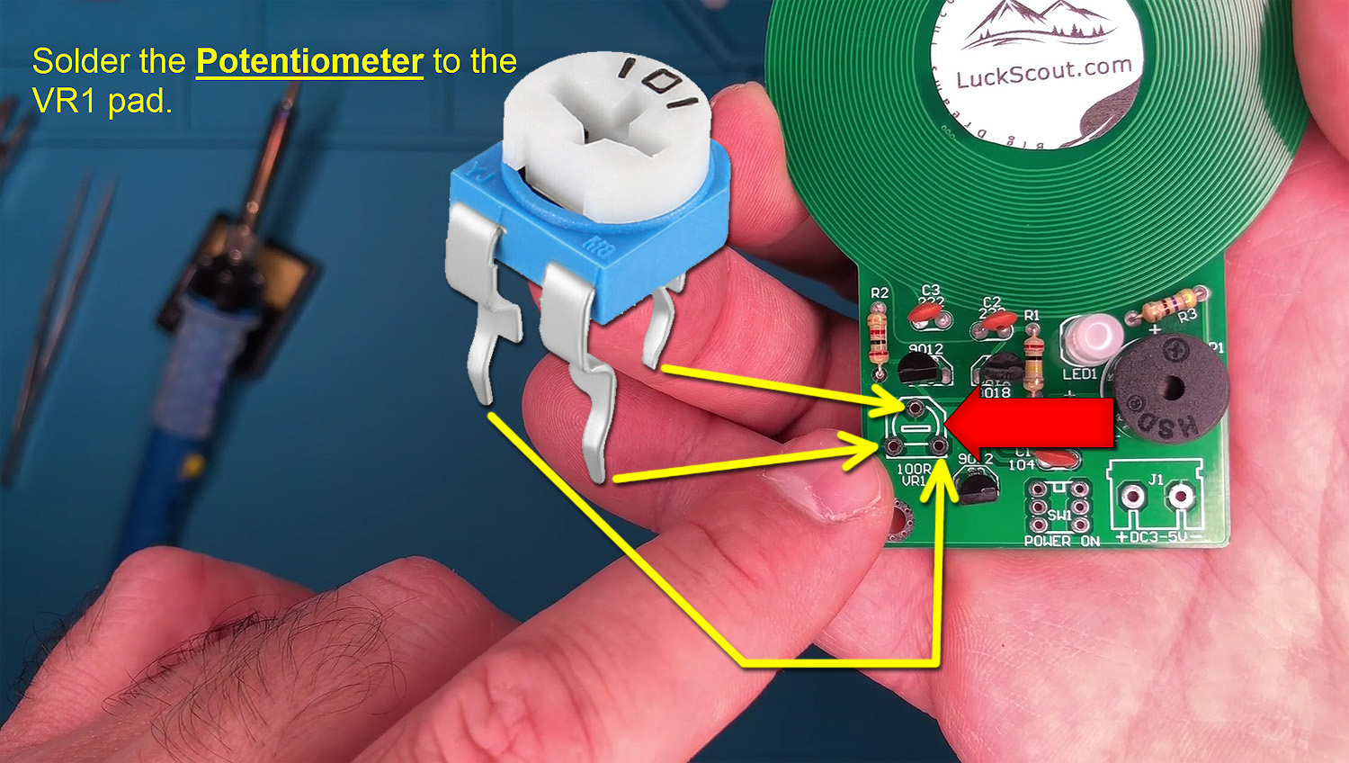
A 100R Potentiometer is a potentiometer with a resistance value of 100 ohms. In a metal detector, this component serves as a variable resistor allowing the adjustment of resistance in the circuit. The 100R potentiometer is likely employed for user-adjustable settings within the metal detector, such as sensitivity control, threshold adjustment, or tuning parameters. By altering the resistance using the potentiometer, users can customize the detector’s performance, allowing for fine-tuning to optimize sensitivity levels, adjust threshold signals, or modify other critical aspects of the metal detection process.
12. KF301 2 Pin Power Socket
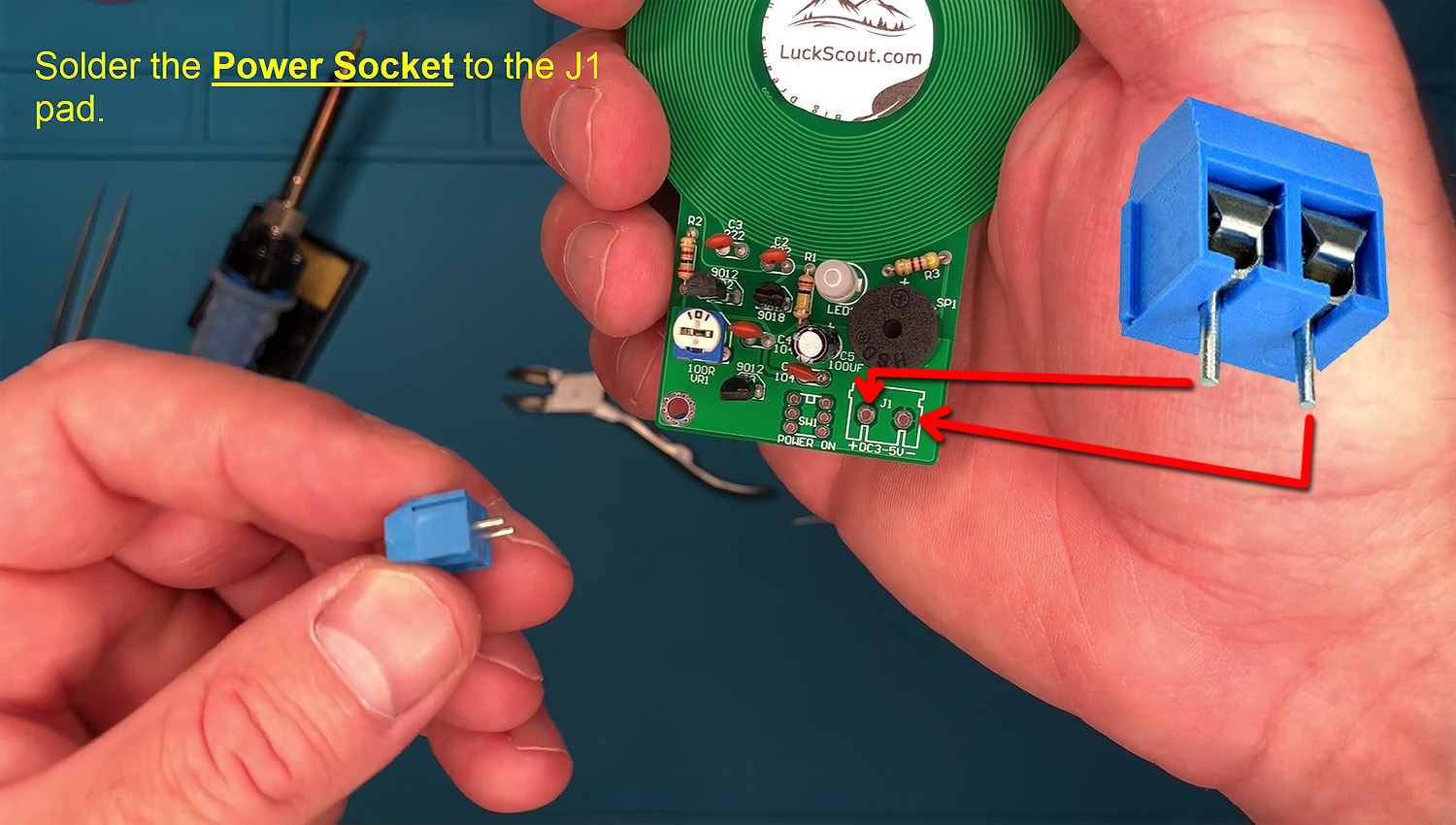
Although it has a long name, this component is very simple, and you will know what it does as soon as you see it. This component enables you to connect the battery holder (explained below) to the metal detector kit. It has to be soldered to the J1 pad:
13. 6x5mm Power Switch
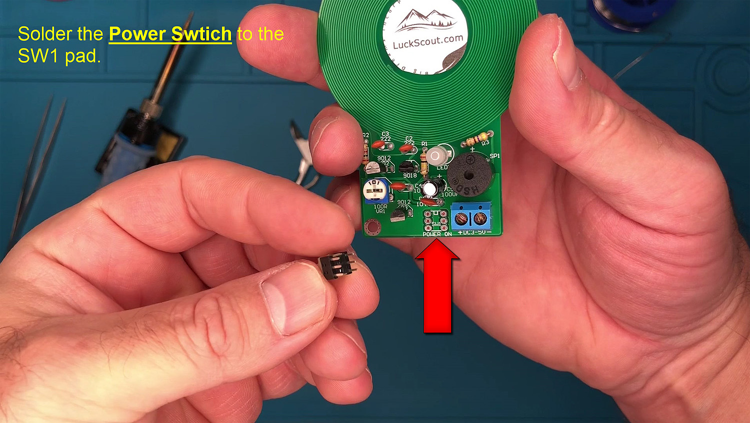
You are almost there. Just solder the 6x5mm Power Switch to the SW1 pad. The 6x5mm Power Switch has 6 legs. You won’t get confused because it is clear how to position the 6x5mm Power Switch correctly:
14. 3 AA Battery Holder
The metal detector kit comes with a 3 AA Battery Holder that needs to be connected to the KF301 2 Pin Power Socket using the red and black wires provided with the battery holder. Connecting them is straightforward, and you can see the process in the video below:
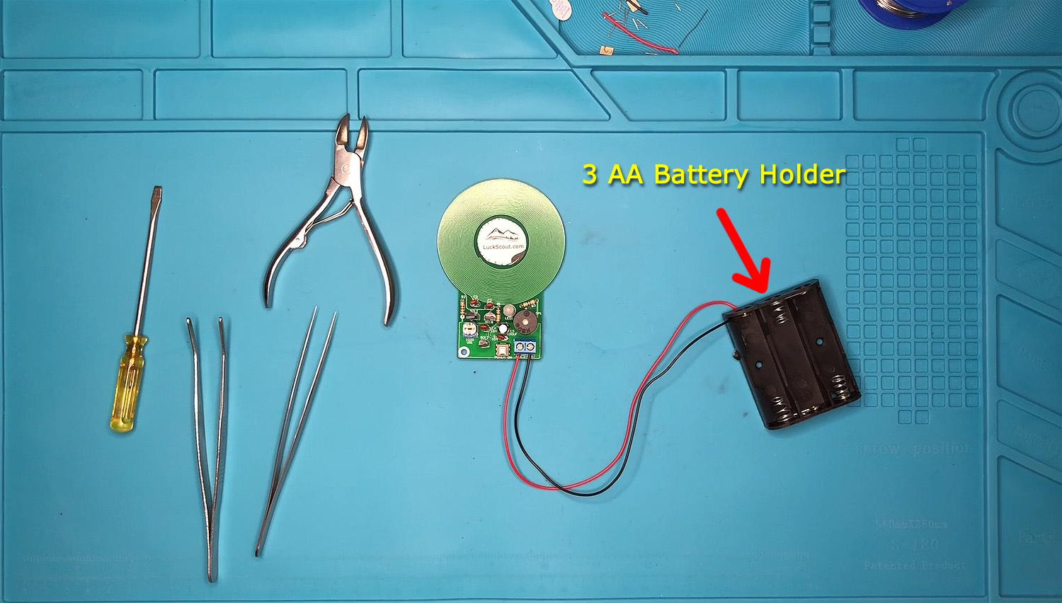
After installing the 3 AA Battery Holder, insert three AA batteries, and then switch on the metal detector. As explained above, it will start buzzing if you have done everything correctly. However, you will need to turn the 100R potentiometer to the right using a screwdriver, as shown in the video below, to optimize sensitivity:

Your Metal Detector
Experience the thrill of a small yet fascinating electronic project with our metal detector kit. Gift it to your kids to help them become acquainted with electronics and science. If you don’t have the tools shown in the video above, you can also order them: